Nuclear vessels, piping, and components require rigorous material verification, as any leakage of radiation or contaminants due to corrosion can lead to critical safety issues. Consequently, systematic research into the corrosive behavior of materials and the resulting stress variations is of paramount importance.
Reflecting these stringent requirements, Ilshin Autoclave’s nuclear power testing systems are engineered to precisely evaluate mechanical properties and durability performance demanded by reactors and industrial sites.

Measurement of
Mechanical Properties

Safe Nuclear
Reactor Testing

Versatile Material
Verification
A specialized testing system for measuring corrosion, cracking, and tensile properties. It is used to verify materials for nuclear vessels, piping, and components, as well as to evaluate mechanical properties required in reactor environments and industrial sites.
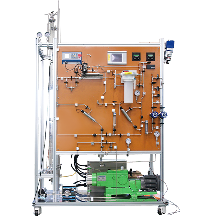
A water quality measurement and circulation system that provides a continuous environment. By optimizing the system through a circulation method and applying diverse control techniques, it maintains stable and consistent conditions. It is used to precisely control factors that directly affect corrosion, such as dissolved oxygen (DO), temperature, pressure, and flow rate.
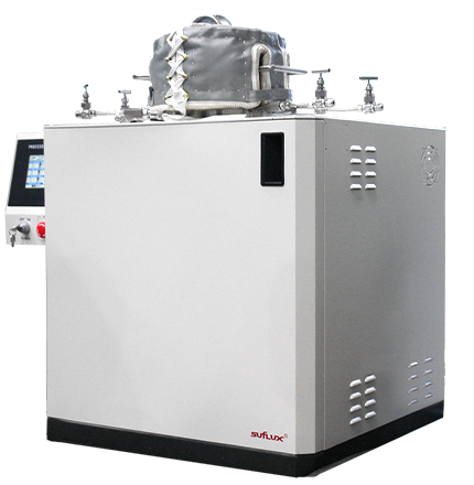
A reactor designed to simulate various reaction environments using flammable hydrogen gas. It features a threaded closure structure to facilitate the easy opening and closing of large-scale equipment. Integrated with pumps, sensors, and controllers, it achieves optimal process conditions and is utilized for research on hydrogen-induced cracking and erosion in metals.
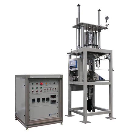
Featuring a structure optimized for repeated testing and supporting various programs for control rod drive operation, this system is designed for stable performance even in corrosive environments. It is used to verify nuclear control rod drive mechanisms under conditions that closely mimic actual operating environments.
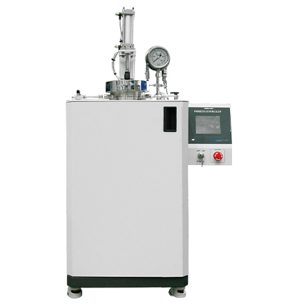
A reactor built to withstand high-temperature, high-pressure, and corrosive environments, capable of performing Stress Corrosion Cracking (SCC) tests. It is utilized for corrosion testing of power plant materials and the evaluation of stress corrosion cracking.
Engineered to minimize thermal impact after samples pass through the chamber, preventing sample damage and ensuring the integrity of corrosion data.
Designed and manufactured in accordance with ASME standards. We ensure maximum safety and reliability through KGS and ASME (U, U2, U3) certifications.
Customizable configurations are available to match specific test principles, including SERT (Slow Extension Rate Test), SSRT (Slow Strain Rate Test), and CERT (Constant Extension Rate Test).
Equipped with high-precision sensors for temperature and pressure to ensure the delivery of highly reliable test data.
With over 20 years of experience in design and manufacturing, we provide stable and highly dependable testing equipment built on accumulated technical know-how.
Our dedicated CS team provides rapid technical assistance throughout the entire lifecycle, including installation, operation, and maintenance.
Based on 100% proprietary domestic technology, we offer superior performance with a highly competitive and reasonable price point.
| Series | SERT | SSRT | CERT |
|---|---|---|---|
| Max Working Temp. (℃) | 250 / 340 / 450 | ||
| Max Working Press. (Mpa) | 20 / 35 | ||
| Rod Speed (mm/min) | 0.1 ~ 0.0000125 (1.25 x E5) | ||
| Rod Stroke (mm) | 50 / 100 | ||
| Capacity (Ton) | 0.5 / 1 / 2 / 5 / 10 | ||
| Vessel Material | STS 316 / INC 625 / HC 276 / Ni200 | ||
| Vessel Volume (L) | 3.78 / 5 / 7.56 | ||
| Specimen Type | Plate / bar | ||
| Q'ty of Electrode | Reference / Count (-) / Working (+) | ||
| Cover Direction | Up / Down | ||
| Control | PLC & PC Control, Graph, Data Save | ||
| Model | Panel | Cabinet | |
|---|---|---|---|
| Max Working Temp. (℃) | 250 / 340 / 450 | ||
| Max Working Press. (Mpa) | 20 / 35 | ||
| Flow Rate (mL/min) | 50 / 100 / 200 / 500 | ||
| Sensor | DO / DH / PH / Conductivity | ||
| MFC | Ar / N2 / H2 | ||
| Tube Material | STS 316 / INC 625 / HC 276 / Ni 200 | ||
| Water Storage | Glass Column / Tank | ||
| Control | PLC & PC Control, Graph, Data Save | ||
| Model | HDT 20 | HDT 50 | HDT 100 |
|---|---|---|---|
| Max Working Temp. (℃) | 400 / 700 | ||
| Max Working Press. (Mpa) | 35 / 60 | ||
| Vessel Volume (L) | 20 | 50 | 100 |
| Working Size (Dia. X Len. mm) | 127 X 310 | 324 X 600 | 430 X 1040 |
| Vessel Material | STS 316 / INC 625 / HC 276 | ||
| Booster System | Gas booster / Gas Compressor | ||
| Control | PLC & PC Control, Graph, Data Save | ||

| Model | CTRS - 2L | CTRS - 1G | CTRS - 2G |
|---|---|---|---|
| Max Working Temp. (℃) | 350 / 500 | ||
| Max Working Press. (Mpa) | 20 / 35 | ||
| Vessel Volume (L) | 2.0 | 3.78 | 7.57 |
| Working Size (Dia. X Len. mm) | 100 X 130 | 127 X 310 | 127 X 620 |
| Vessel Material | STS 316 / INC 625 / HC 276 / Ni 200 / Ti | ||
| Control | PLC & PC Control, Graph, Data Save | ||
| Option | Reference Electrode, Working & Counter Electrode (Conax Fitting, Radiation Tube) | ||
| Model | FAC - 2L | FAC - 1G | FAC - 2G |
|---|---|---|---|
| Max Working Temp. (℃) | 350 / 500 | ||
| Max Working Press. (Mpa) | 20 / 35 | ||
| Vessel Volume (L) | 2.0 | 3.78 | 7.57 |
| Working Size (Dia. X Len. mm) | 100 X 130 | 127 X 310 | 127 X 620 |
| Vessel Material | STS 316 / INC 625 / HC 276 / Ni 200 / Ti | ||
| Control | PLC & PC Control, Graph, Data Save | ||
| Option | Reference Electrode, Working & Counter Electrode (Conax Fitting, Radiation Tube) | ||


Customer Support
042-931-6100A/S
042-602-8018ⓒ Ilshinautoclave 2025, All RIGHTS RESERVED