

Our High-Pressure Reactors are engineered and manufactured in specialized categories—including multipurpose, polymerization, ultra-high temperature/pressure, and specialized R&D/production reactors—tailored to specific application goals and process conditions.
By integrating the main reactor with a selective range of functional auxiliary components, we offer customized system configurations. This approach comprehensively reflects client requirements, including operational convenience, cost-efficiency, experimental objectives, and production throughput.

Synthesis Reaction

Decomposition
Reaction

Catalytic Reaction
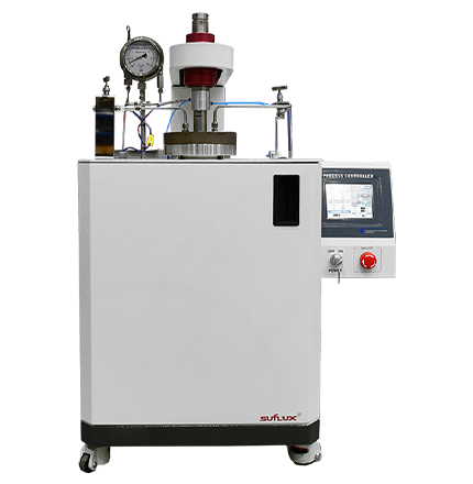
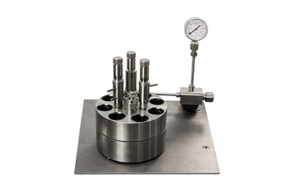
A compact, bench-top reactor designed for ease of operation and space efficiency. It is widely utilized for various research purposes, including synthesis, decomposition, and catalytic reactions.
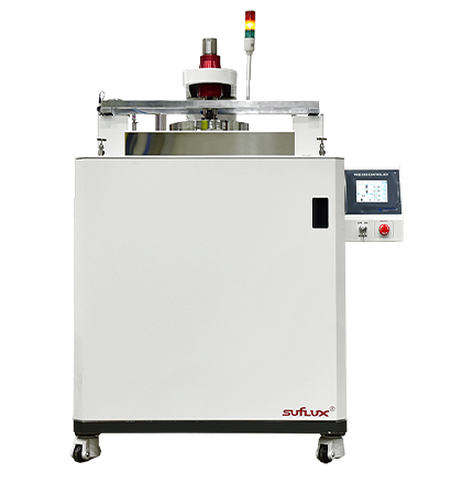
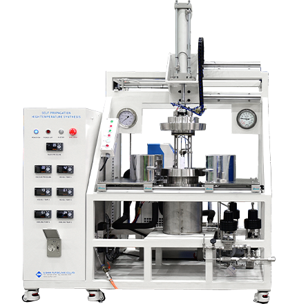
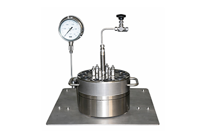
A versatile stand-type reactor that can be configured with various specifications depending on its intended use. It is ideal for diverse research fields such as hydrothermal synthesis, pyrolysis, and Self-propagating High-temperature Synthesis (SHS).
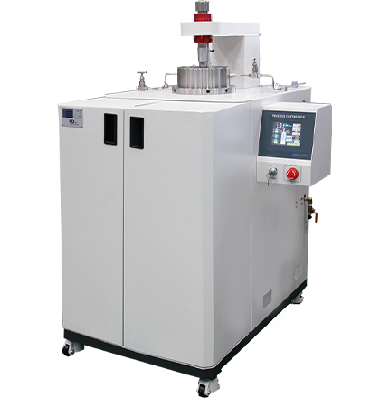
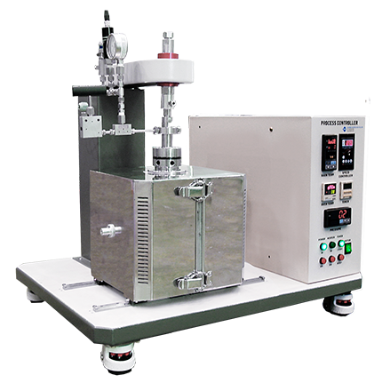
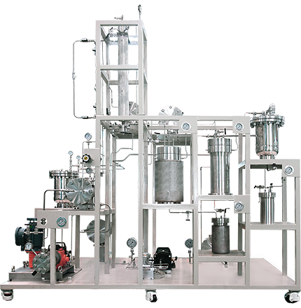
Custom-engineered high-pressure reactors for specific industrial and research purposes. This category includes systems for ultra-high temperature/pressure, polymerization, hydrogenation, SHS, as well as uniform and continuous processes.
We design and manufacture pressure vessels in strict accordance with ASME standards. Safety and reliability are guaranteed through domestic KGS inspections and international ASME U, U2, and U3 certifications.
For enhanced safety, our systems feature a dual-layer protection design: an automated software-level emergency stop (Primary), followed by a secondary mechanical safety valve that automatically vents pressure in case of an anomaly.
Precise internal temperature is maintained through advanced heaters and high-performance insulation. The integration of PID control via our dedicated controller ensures highly accurate and stable thermal management.
Our systems are engineered for operational ease with a convenient vessel opening and closing mechanism. We provide optimized pressurization tailored to specific conditions and support continuous feeding for various samples.
Leveraging 30 years of accumulated expertise, we provide high-integrity piping solutions. We select materials that remain stable under high pressure and design layouts that allow operators to monitor the process flow at a glance.
The control panel features an intuitive interface for easy operation. Its stable and superior performance enhances overall equipment management efficiency.
| Series | HR-B-500 | HR-S-1000 | HR-S-2000 | HR-S-5000 |
|---|---|---|---|---|
| volume (㎖) | 500 | 1000 | 2000 | 5000 |
| Design Condition | 100bar, 200℃ | MAX. 200bar / MAX. 350℃ | ||
| Gasket | O-ring(Viton, Kalrez) | O-ring(Viton, Kalrez), Metal(STS304-316, Ni) | ||
| Electricity | AC220, 1PH(single-phase) | Consultation | ||
| Magnedrive | Available | |||
| RPM | 320 RPM | 320 RPM - Variable | ||
| Material | STS304, STS316, HC276, INC600, INC625, Ni, Ti | |||
| Liner | Teflon, Peek, Ti, Ni, STS304, STS316, HC276, INC600, INC625 | |||
| Impeller | Consultation | |||
| Equipment Voltage | - | Consultation | ||
| Equipment Power | - | Consultation | ||
| Equipment Size (WxDxH) | - | 730 X 680 X 1,200 | 800 X 720 X 1,200 | 1000 X 760 X 1,700 |
| Equipment Weight (kg) | 35 ~ 60 | 65 | 75 | 90 |
| option | - | Cooling coil, gas booster, hopper, condenser, pneumatic valve, regulator, heater (jacket type), TC (RTD, T, etc.), body cover (movable up, down, front and backward), sensor calibration | ||
| Model | Hydrogenation Reactor |
|---|---|
| Working Capacity | 500㎖ ~ 100ℓ (Consultation) |
| Working Temp. | -30 ~ 300℃ (Consultation) |
| Working Pressure | Vacuum ~ 300bar (Consultation) |
| Magnedrive RPM | Low Speed ~ 500RPM (Consultation) |
| Series | UTR-100 | UTR-200 | UTR-300 | UTR-500 | UTR-1000 | UTR-2000 |
|---|---|---|---|---|---|---|
| Volume (㎖) | 100 | 200 | 300 | 500 | 1000 | 2000 |
| Magnedrive | N/A | Available | ||||
| RPM | X | 320 RPM - Variable | ||||
| Design Condition | MAX. 500bar / MAX. 500℃ | |||||
| Gasket | Metal (STS316, HC276, INC600-625, Ni, Ti) | |||||
| Electricity | Consultation | |||||
| Material | STS304, STS316, HC276, INC600, INC625, Ni, Ti | |||||
| Liner | Teflon, Peek, Ti, Ni, STS304, STS316, HC276, INC600, INC625 | |||||
| Impeller | Consultation | |||||
| Series | HR-PR-500 | HR-PR-1000 | HR-PR-2000 | HR-PR-5000 |
|---|---|---|---|---|
| Volume (㎖) | 500 | 1000 | 2000 | 5000 |
| Equipment Voltage | Consultation | |||
| Equipment Power | Consultation | |||
| Equipment Size (WxDxH) | 600 X 560 X 1,000 | 730 X 680 X 1,200 | 800 X 720 X 1,200 | 1000 X 760 X 1,700 |
| Design Condition | MAX. 50bar / MAX. 200℃ | |||
| Gasket | O-ring(Viton, Kalrez), Metal(STS304-316, Ni) | |||
| Electricity | Consultation | |||
| Magnedrive | Selectable | |||
| RPM | 320 RPM - Variable | |||
| Material | STS304, STS316, HC276, INC600, INC625, Ni, Ti | |||
| Liner | Teflon, Peek, Ti, Ni, STS304, STS316, HC276, INC600, INC625 | |||
| Model | Self-Propagating Combustion Reactor |
|---|---|
| Working Capacity | 500㎖ ~ 100ℓ (Consultation) |
| Working Temp. | 100℃ (Consultation) |
| Working Pressure | Vacuum ~ 200bar (Consultation) |
| Model | Uniform Parallel Reactor |
|---|---|
| Working Capacity | 300㎖ ~ 100ℓ (Consultation) |
| Working Temp. | -30 ~ 350℃ (Consultation) |
| Working Pressure | Vacuum ~ 350bar (Consultation) |
| Magnedrive RPM | Low Speed ~ 100RPM (Consultation) |
| Model | Working Capacity | Working Temp. | Working Pressure | Material | Heating Unit |
|---|---|---|---|---|---|
| Continuous Process Reactor Main Reactor - 2SET |
0.5ℓ (Inside Size : φ 65 ㎜ X 155 ㎜) | 350℃ (Consultation) | ~ 20kg/㎠ | HC276 | Ceramic Band Heater |
| Continuous Process Reactor Pressure Filtering Reactor - 2SET |
~ 10kg/㎠ | SUS316 |
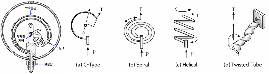
Pressure can be measured through various methods, including liquid-column manometers (using fluid), elastic pressure gauges (utilizing the elasticity of tubes or diaphragms), and electrical pressure gauges (measuring electrical variations). Among these, elastic pressure gauges—specifically the Bourdon tube pressure gauge—are widely utilized for industrial applications and high-pressure environments.
The principle of the Bourdon tube relies on its tendency to straighten when pressurized, causing the tip to move. This displacement is then measured to determine the pressure. Available in various forms such as C-type, helical, spiral, and twisted, these gauges operate based on the principle of elastic deformation in accordance with Hooke’s Law.
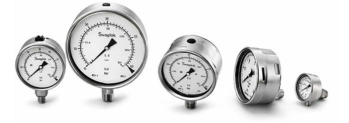
A Pressure Sensor refers to a device or system (such as pressure-based flowmeters) that responds to applied pressure. This category includes 'pressure gauges' for measuring atmospheric pressure and 'vacuum gauges' for measuring pressures below atmospheric levels.
In modern engineering, the term 'pressure sensor' typically refers to a device that converts pressure levels into electrical signals. Key types include resonant, piezoelectric, strain gauge, and capacitive pressure sensors. These sensors are indispensable in both daily life and industrial sectors, widely used in fire suppression pressure maintenance systems, water supply units, refrigeration cycles, and various other industrial sites.

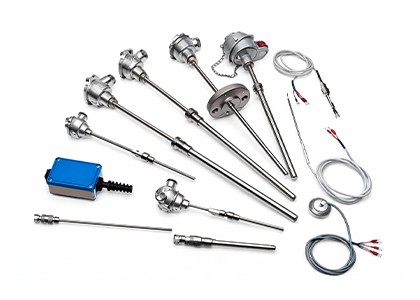
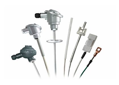
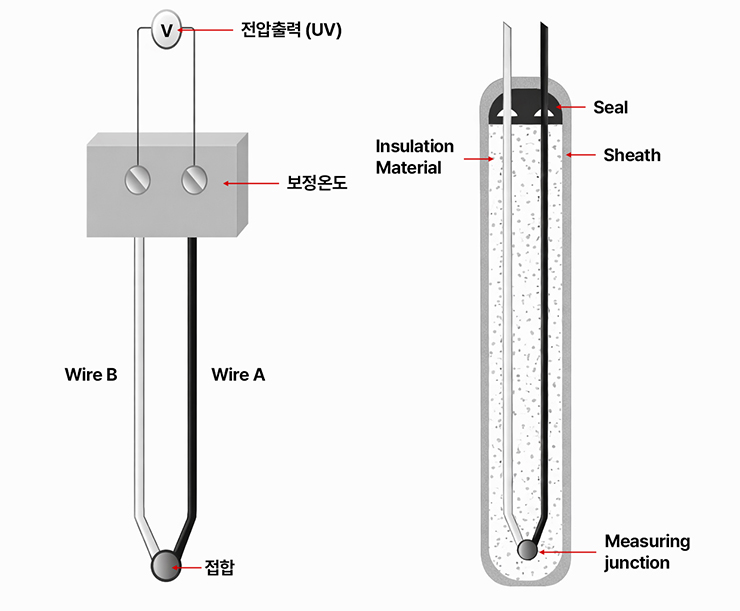
When two dissimilar metal wires are joined at both ends and a temperature difference is maintained between the two junctions, a proportional thermoelectromotive force (thermo-EMF) is generated. A thermocouple is a temperature measurement system that displays temperature by measuring this EMF using a DC millivoltmeter (mV) or a potentiometer.
This phenomenon, where an electromotive force (EMF) is created within a closed circuit formed by two different metallic conductors under a temperature gradient, is known as the Seebeck effect. By maintaining one junction (the reference or cold junction) at a baseline temperature of 0°C and placing the other (the measuring or hot junction) on the object to be measured, the temperature can be accurately determined through the resulting EMF. This combination of two dissimilar metallic conductors is called a thermocouple.
| JIS Code | Positive Leg | Negative Leg | Temperature Range | Former Code |
|---|---|---|---|---|
| K | Chromel | Alumel | - 200 ℃ ~ 1000 ℃ | CA |
| J | Iron | Constantan | 0 ℃ ~ 600 ℃ | IC |
| T | Copper | Constantan | - 200 ℃ ~ 300 ℃ | CC |
| E | Chromel | Nisil | - 200 ℃ ~ 700 ℃ | CRC |
| N | Nicrosil | Platinum | - 200 ℃ ~ 1200 ℃ | - |
| R | Platinum 13% Rhodium | Platinum | 0 ℃ ~ 1400 ℃ | PR |
| S | Platinum 10% Rhodium | Platinum | 0 ℃ ~ 1400 ℃ | - |
| B | Platinum 30% Rhodium | Platinum 6% Rhodium | 0 ℃ ~ 1500 ℃ | - |
Maximum temperatures for types K, J, T, E, and N are for wire diameter Φ 3.2, while types R, S, and B are for wire diameter Φ 0.5.
Thermocouples are categorized into various types, including K, J, T, E, N, R, S, and B. Among these, Types K, J, T, and E are the most widely used in industrial applications. In particular, the Type K thermocouple is the most popular choice due to its broad operating range and excellent versatility.
When selecting a thermocouple, it is crucial to choose the type that best fits your specific measurement conditions and objectives, comprehensively considering factors such as the temperature range, installation and operating environment, and required accuracy.
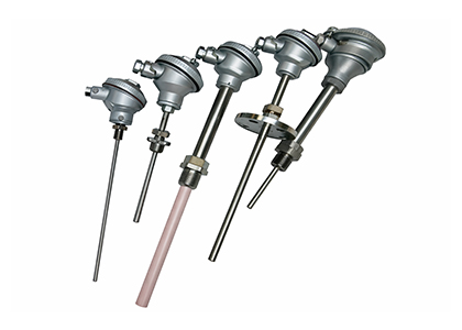
A Thermowell is a drilled bar stock type protection tube commonly used to extend the lifespan of thermocouples under harsh conditions, such as corrosive gases or liquids, high temperatures, high pressures, vibrations, impacts, or high flow velocities.
To withstand these demanding environments, they are typically manufactured from robust metal materials, including Stainless Steel (SUS), Hastelloy, Monel, Nickel, Titanium, and their respective alloys.
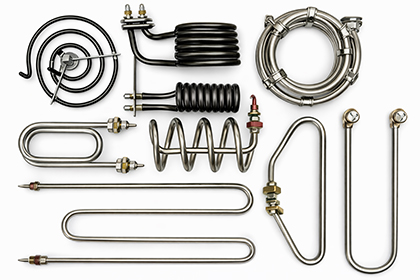
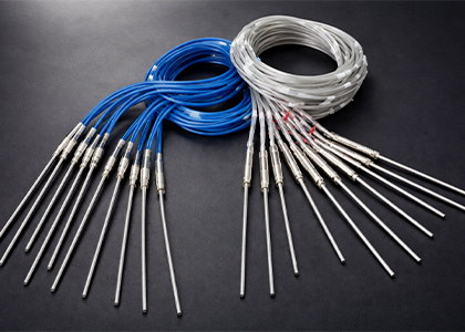
This electric heater is manufactured by winding heating wires inside a base pipe made of steel, stainless steel, or copper, which is then filled with magnesium oxide (MgO) for insulation and bent into various shapes to suit specific applications. It is the most widely utilized heating solution across diverse industrial sectors.
It is applied in various processes such as air heating, dryer internal heating, mold and thermal molding, solder melting, film bonding, as well as high-temperature and preheating for electric heaters and space heating. It is most commonly utilized as an immersion-type heater.

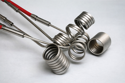
This heater features a heating coil made from premium high-temperature resistance wires precisely wound onto a ceramic core and positioned in close proximity to the inner wall of the sheath. The assembly is then solidly compressed and solidified with high-purity magnesium oxide (MgO), which offers exceptional thermal conductivity and high-temperature insulation resistance.
It is widely applied across a diverse range of industries, including injection and extrusion molding, automated and film packaging, footwear manufacturing, press dies, and electronic heating equipment

This heater is designed by welding flanges and various metal components onto metal pipes, allowing the heating element to be directly immersed into the liquid. This method achieves near-100% thermal efficiency by minimizing heat loss.
It delivers high power capacity even at approximately half the size of conventional market products, making it ideal for equipment miniaturization while ensuring stable performance. It is widely used in various thermal processes involving water, chemical solutions (organic solvents, acids, alkalis), resins, wax, dehydration salts, electric boilers, solar water heaters, freeze protection systems, alcohol sterilizers, and ultrasonic cleaners.
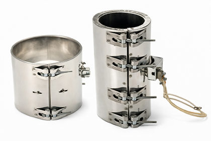
This heater can be easily attached to extruders, injection machines, and cylinders, providing excellent thermal conductivity. Its internal structure utilizes natural or processed mica, offering superior insulation that eliminates the risk of electrical leakage. The exterior casing is custom-manufactured from stainless steel (SUS) or steel, depending on specific requirements.
Designed to maintain an optimal watt density for an extended service life, this heater features a screw-type fastening system for quick and easy installation. It is utilized across a wide range of industrial applications, including injection molds, thermal extruders, rubber molds, presses, crimping and cutting processes, as well as laboratory and medical equipment.
As an advanced upgrade to conventional mica-insulated band heaters for injection machines, this product is manufactured using high-density filling and swaging processes. This compressed construction ensures an extended service life and superior thermal transfer performance.
By generating high heat directly at the contact surface, it significantly enhances productivity, while its high-density, high-compression structure makes it ideal for processes requiring intense thermal energy. Furthermore, its excellent resistance to corrosion and oxidation, combined with exceptional durability, ensures stable long-term operation. It is widely applied to injection and extrusion machines, pipe insulation, and various industrial heating applications.

In manufacturing processes, when gases or liquids are discharged through pumps or flow through piping, temperature variations can trigger a phase change. This often leads to powder formation or solidification, which can cause significant process defects.
To prevent such issues, Heating Jackets provide a stable process environment by uniformly heating and maintaining the insulation of the target equipment. They are widely applied to facilities requiring consistent temperature control and thermal insulation, such as semiconductor manufacturing processes, chemical plants, piping, pumps, storage tanks, and reactors.
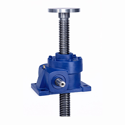
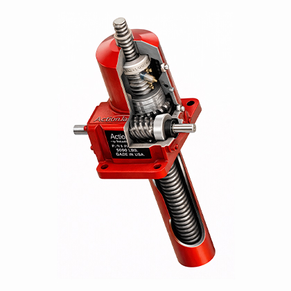
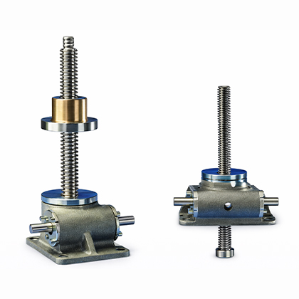
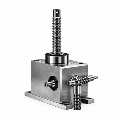
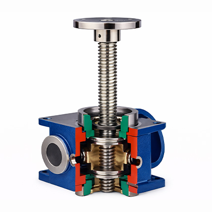
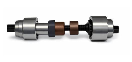
A Jack is a device used to lift heavy loads vertically with minimal force, providing stable positioning for workpieces or structures through various driving mechanisms such as screw, gear, or hydraulic types. The main types include Screw Jacks, Ball Screw Jacks, Miniature Screw Jacks, and Rack Jacks. Among these, Screw Jacks and Ball Screw Jacks feature a mechanism that converts rotary motion into linear motion to drive the load directly, allowing them to function as linear actuators.
In particular, Ball Screw Jacks offer higher speed and efficiency compared to standard Screw Jacks, making them ideal for processes requiring high precision and sophisticated position control. Depending on the design, Screw Jacks are categorized into Translating Screw (Axial lifting) and Rotating Screw (Nut lifting) types, with the option for manual or motor-driven operation. When selecting a jack, it is essential to specify the appropriate model by comprehensively evaluating operating conditions, including load capacity, travel speed, and required torque.
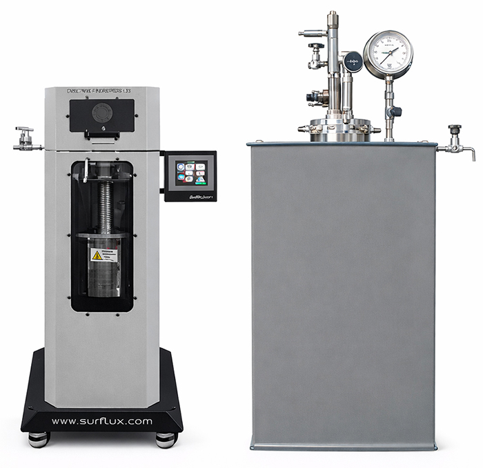
The Body Up & Down Series is designed to prioritize user safety and operational convenience, featuring a system that moves the reactor vessel vertically for maximum efficiency.
As laboratory reactors have become larger and more difficult to handle manually, we have implemented a structure where the reactor cover remains fixed while the body (vessel) is driven upward and downward via pneumatic or hydraulic systems. This design allows for the safe and easy charging and discharging of samples, significantly minimizing the physical strain on operators.
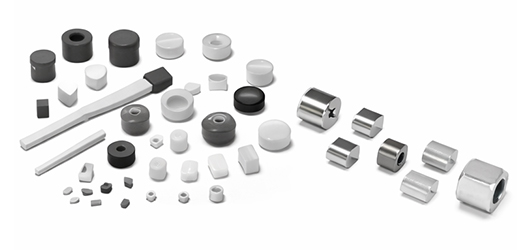
Gaskets, O-rings, and seals are essential components used between grooves or contact surfaces in rotating parts and connecting joints to prevent the leakage of fluids such as water and gas. They are vital in any application requiring compression sealing and are widely utilized across all industrial sectors.
These components are manufactured from a variety of materials to suit specific requirements. The types are highly diverse—including Metal Gaskets, O-rings, Teflon Seals, and Asbestos Gaskets—and their application methods vary depending on the intended use and environmental conditions.
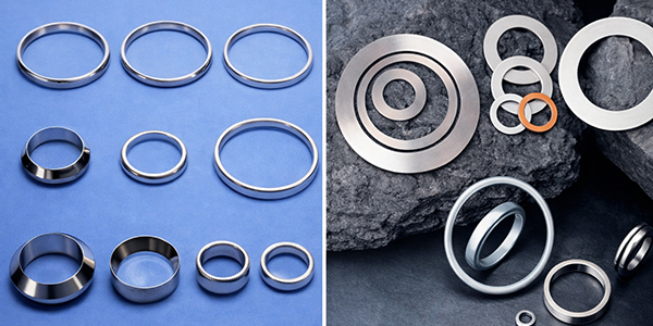
These components are essential for pipe flanges, pressure vessels, reactors, vessels, and valves in processes handling high-temperature/high-pressure steam, gas, hot oil, oil gas, and solvent vapors.
They are available in a wide range of materials, including Nickel, Steel, Aluminum, and Titanium. It is crucial to select the appropriate material based on specific operating conditions, such as the required temperature, pressure, and the type of gas being handled.
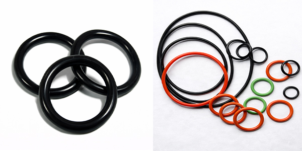
Made from natural or synthetic polymer resins, O-rings are representative sealing devices known for their simple structure and ease of use. They are widely utilized in both daily life and throughout various industrial sectors.
However, in high-temperature environments, the physical properties of the material can change, potentially leading to a decrease in sealing effectiveness and compression performance. Consequently, their use may be restricted under extreme temperature conditions. Depending on the intended purpose and environment, O-rings are manufactured from a diverse range of materials, including Natural Rubber, NBR, Silicone, Viton (FKM), Acrylic Rubber, Butyl Rubber, Chloroprene, and Urethane.
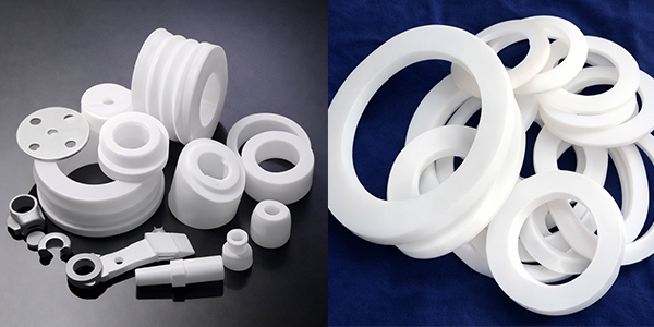
With an exceptionally wide operating temperature range from -200°C to 260°C, Teflon (PTFE) is widely used in chemical processes due to its outstanding resistance to almost all chemicals, with the exception of chlorine trifluoride and molten alkali metals.
Its excellent chemical, corrosion, heat, and acid resistance allow it to maintain stable performance even in various solvents and high-temperature environments. Furthermore, it is highly resistant to shock and vibration, making it suitable for a diverse range of industrial sectors. Additionally, its superior electrical insulation and low dielectric constant minimize static electricity, leading to its extensive use in the electrical and electronics industries.
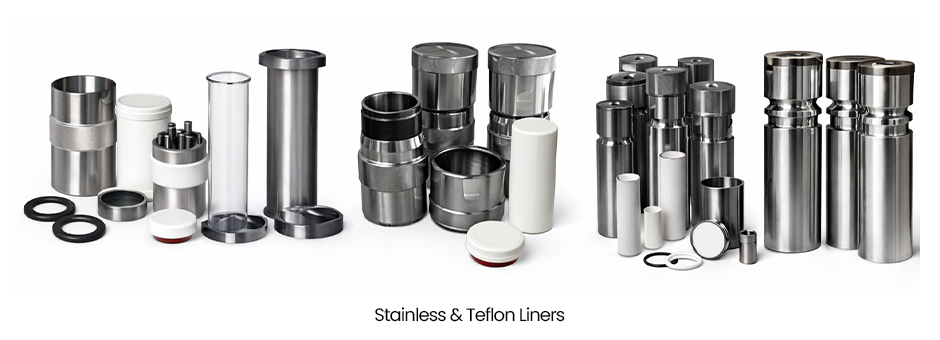
A Liner is a specialized component manufactured by selecting materials optimized for the specific characteristics of the fluids and gases it contacts. For the exterior, metal materials such as SUS (Stainless Steel), Nickel, Inconel, and Hastelloy are primarily used to ensure high durability and semi-permanent use.
The interior is designed with polymer resins such as Teflon (PTFE), PEEK, or PE, allowing for easy replacement in case of wear or damage caused by repetitive contact. Depending on the operating temperature, pressure, and the nature of the substances being handled, these polymer liners can be used independently or inserted into a metal shell to form a composite structure.
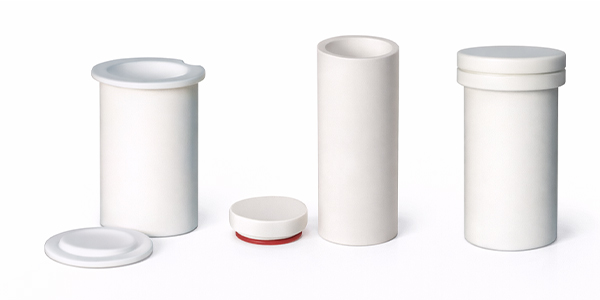
These vessels utilize special polymer resins such as Teflon (PTFE), PEEK, and PE, which are engineered to withstand high-temperature and high-pressure reaction conditions. Thanks to their exceptional physical properties even in extreme environments, they are widely used in applications requiring superior heat resistance, chemical inertness, electrical insulation, a low coefficient of friction, and oil resistance.

By applying metal materials such as SUS, Nickel, Inconel, and Hastelloy, these vessels ensure stable operation in high-temperature/high-pressure environments, as well as under conditions demanding high corrosion and chemical resistance.
They can be manufactured using a single material or designed with a multi-metal composite structure—such as a Nickel interior combined with a SUS exterior. This approach maximizes the unique advantages of each material, allowing for a customized solution optimized for the specific intended use.
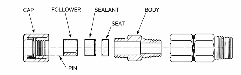
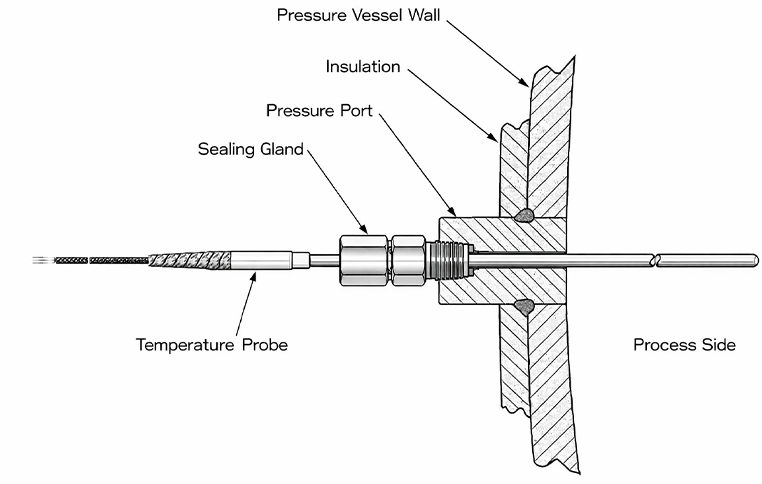
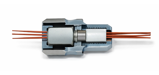
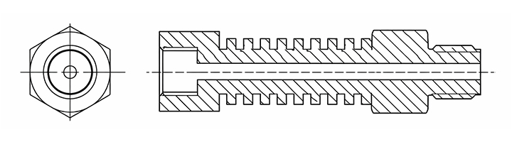
A Conax Fitting is a specialized sealing solution designed to prevent pressure leakage when passing power leads or measurement signal electrodes and wires through a boundary in high-temperature, high-pressure, or vacuum environments.
Due to its structural requirement—where wires or electrodes must pass directly through the fitting—it is a highly differentiated product compared to standard fittings that only require simple sealing. It must simultaneously ensure stable electrical insulation and airtight integrity even under extreme conditions.
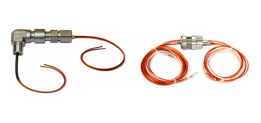
These fittings are applied to extreme-environment facilities such as pressure vessels, autoclaves, storage tanks, piping, and furnaces, where they facilitate the insertion of sensors for detecting temperature, flow, and materials, as well as the transmission of various measurement signals. Furthermore, they deliver highly reliable performance not only in high-pressure/high-temperature conditions but also in environments handling hazardous and toxic substances.
Cooling pipes are a general category of tubing designed to dissipate heat and protect temperature-sensitive devices, such as valves and Conax fittings, from thermal damage. Based on the cooling mechanism, they are classified into Air-Cooled and Water-Cooled systems.
The Air-Cooled type features a corrugated or finned structure to increase the surface area in contact with air, thereby lowering the temperature. The Water-Cooled type utilizes a water jacket surrounding the pipe, through which cooling water flows to dissipate heat.
The Air-Cooled type achieves cooling through heat exchange with the air by increasing the surface area via cooling fins. It is categorized into Natural Convection (Passive) and Forced Air (Active) cooling, the latter of which uses fans. While its simple structure makes maintenance and management easy, its cooling efficiency is relatively limited compared to water-cooled systems.
The Water-Cooled type removes heat by circulating a coolant, such as water. Because water has a high specific heat capacity, this method offers superior cooling efficiency compared to air-cooled systems. It continuously circulates and regulates the coolant through a jacket and pump system. This type features a relatively complex structure and requires regular maintenance.
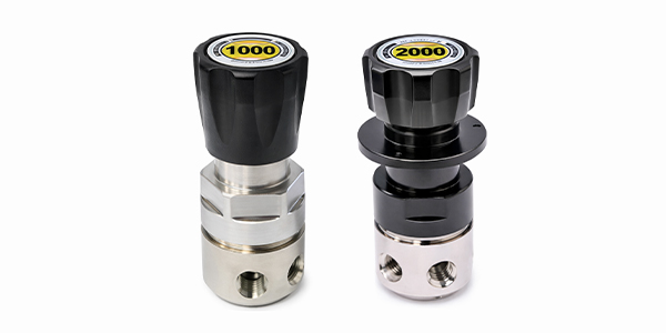
A Pressure Regulator Valve (PRV), commonly referred to as a Regulator, is a device designed to maintain a consistent downstream (outlet) pressure regardless of fluctuations within the upstream (inlet) pressure range.
The operating principle is based on a balance of forces: when the fluid pressure exceeds a pre-determined set pressure, it overcomes the force of the spring pressing against the diaphragm. This action causes the valve outlet to open, allowing the fluid to be discharged (relieved) until the balance is restored. Users can precisely set their desired pressure by adjusting the tension of the spring that acts upon the diaphragm.
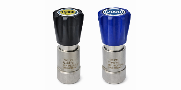
A Back Pressure Regulator (BPR) operates on the opposite principle of a standard pressure regulator; it is designed to consistently maintain the upstream (inlet) pressure at a desired set point.
Our BPRs are capable of handling inlet pressures up to 15,000 psi. To ensure leak-proof performance, we apply specialized sealing types optimized for the specific characteristics of the gas or liquid being handled.
A Needle Valve is a type of flow control valve that utilizes a long, tapered stem to precisely regulate the volume of fluid passing through an orifice. It is a manual valve that controls flow rates or shuts off fluid and gas streams by adjusting the extent to which the stem obstructs the flow path.
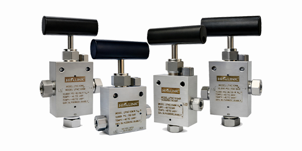
While similar in appearance to standard needle valves, high-pressure models incorporate unique designs and specially selected materials for high-pressure operation. While the body is typically constructed from Stainless Steel (SUS), specialized alloys such as Titanium, Nickel alloys, Inconel, and Monel are used depending on the media (fluid/gas) requirements.
For perfect sealing under extreme pressure, internal components are made from metals and high-performance polymers. The stem is primarily made of SUS, while the sealing components utilize specialized resins such as PCTFE, PEEK, VESPEL, Buna-N, and Teflon. Based on the flow direction, body configurations include Straight, Angle, 3-Way/1-on, and 3-Way/2-on Pressure types. With a wide range of pressure ratings and port sizes available, users can select the ideal valve for their specific conditions. These valves can handle pressures up to 150,000 psi (approx. 10,000 bar) and operate within a temperature range of -55°C to +300°C, depending on the polymer resin used.
An Air Operated Valve (AOV) is a type of valve that uses pneumatic pressure to open and close. Similar to a needle valve, it utilizes a stem to regulate the flow of fluid through a flow path; however, it differs in that the stem is actuated by pneumatic pressure rather than manual operation.Because it relies on air pressure, an AOV carries a lower risk of explosion compared to valves operated by electrical signals, making it an ideal choice for hazardous environments. Furthermore, since it can operate with a relatively low air pressure of approximately $5kgf/cm^2$, it can be easily deployed in any location where a pneumatic supply is available.
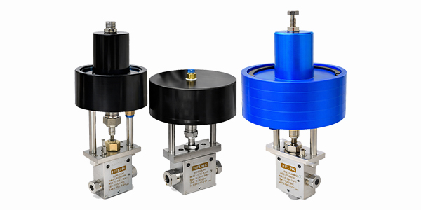
AOVs are widely used in automated processes because they allow for indirect control via electrical signals through a pneumatic control system. A typical example involves using a solenoid valve, which responds to electrical signals, as the pneumatic pilot valve; the regulated air pressure then actuates the AOV to achieve full automation.
Depending on the default state of the valve, they are classified into Normally Closed (NC) and Normally Open (NO) types. Furthermore, various body configurations are available based on the flow path, such as Straight, Angle, 3-Way/1-on, and 3-Way/2-on Pressure types. This variety in pressure ratings and port sizes allows for the selection of the optimal AOV for any operating condition. These valves can handle pressures up to 40,000 psi (approx. 4,000 bar) and typically operate within a temperature range of -55°C to +150°C, depending on the physical properties of the polymer resins used in the interior and head sections.
– Normally Closed (NC) Type: The valve remains closed by default and opens only when pneumatic pressure is applied.
– Normally Open (NO) Type: The valve remains open by default and closes only when pneumatic pressure is applied.
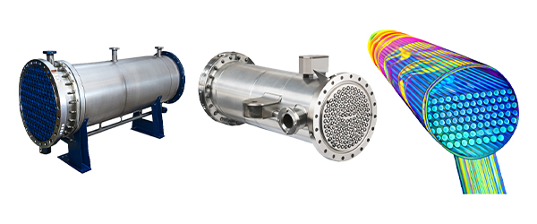
A Condenser is a device designed to cool vapor and convert it back into a liquid state (condensation). The process involves facilitating heat transfer and exchange from the vapor to a coolant (water or gas) through indirect contact via a metal surface, resulting in the cooling and subsequent liquefaction of the vapor.
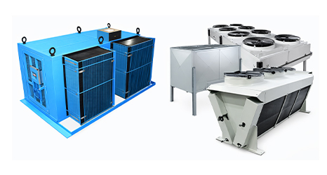
Air-Cooled Condenser: Uses natural or forced air circulation for condensation. Due to its lower heat transfer efficiency, which results in higher condensing temperatures and pressures, it is primarily limited to small-scale Freon refrigeration units.
Water-Cooled Condenser: Removes the heat of condensation by passing cooling water through the condenser piping. These units offer a superior heat transfer coefficient compared to air-cooled models and are widely utilized in large-capacity Freon and Ammonia refrigeration systems.
The structure of a condenser typically involves a long, continuous tube (often in a coil or dense configuration) to transfer heat to the surrounding environment. The vapor paths are mainly constructed from metals with high thermal conductivity, such as copper or aluminum. To enhance heat dissipation, cooling fins (thin sheets of thermally conductive metal) are attached to increase the surface area, thereby maximizing efficiency. Additionally, condensers may feature fans for forced-air cooling across the fins, while large-scale industrial condensers often utilize pumps to circulate water or other liquid coolants.
Various types of condensers are manufactured to accommodate different scales (from compact to large-capacity) and refrigerants like Freon or Ammonia(NH3):
Among these, Water-Cooled Condensers are the most commonly used, with the Horizontal Shell and Tube type being the industry standard for its versatility and efficiency.


Customer Support
042-931-6100A/S
042-602-8018ⓒ Ilshinautoclave 2025, All RIGHTS RESERVED